
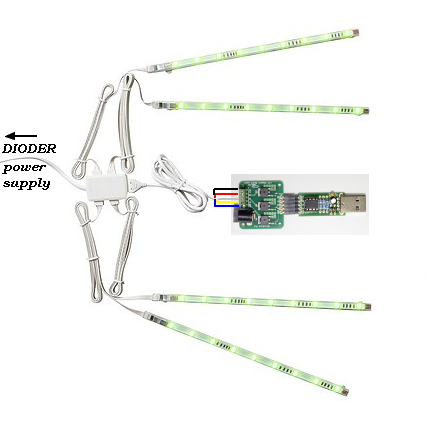
I’m gonna use this to get Ambilight on my pc. SO let’s recap to see if i have everything right:
-Cut the wire and plug them in Adapter
-PLug adapter into blinkstick pro
-blinkstick goes in computer
-Power supply goes in adapter ???
Does not work without blue for me.
Correct order should be like this:
- Everything DISCONNECTED
- Cut wire and connect to LED adapter as described by @p0ke
- LED Adapter must be connected to the BlinkStick Pro
- Connect Blinkstick Pro with LED adapter to the computer
- Connect power supply to the LED adapter
Need to check but can’t find a DIODER set in the office now. Very strange as it shouldn’t require the ground to be connected, because LEDs have only VCC and R, G and B pins.
Ok so no more power supply into Dioder, got it.
Well thank you, i managed to understand everything.
I’ll try without ground and see how it works.
Thanks again for your help everyone
Only as a very simple help:
So there is no need for a additional power supply.
No problem for me 
Dioder power supply doesn’t fit in Adaptater 
DIODER POWER SUPPLY fit in DIODER ADAPTER. If not, then you need to call IKEA!
I think you still want to put the DIODER Power Supply direktly in the BlinkStick adapter what of course does not work!
Please take a look at my schematic, there is no Power Supply at the LED Adapter!
Edit: Updated my schematic above with an additional hint.
Well it looks like i have everything right here, and nothing lights up (i’m in inverse mode)
Hmmm… Wired like I have shown in the photo above?
Black: VCC
Red: R
White: G
Yellow: B
Blue: GND
Even if Arvy says there is no need for the blue one 
Yes, everything seems right
After you opend this thread I´ve tried it with a new Dioder and I know have a nice Ambylight for my Monitor. Maybe IKEA changed something regarding the colors of the wires or so…For me it works perfect like shown in the posts…
You have the Dioder with 4 strips, right? Not with the 4 buttons?!?
Yes of course.
Which wires could’ve been swapped ?
Open the controller of the Dioder and take a look at the wires.
Yup. Alright i see:
-Black linked to B
-Yellow linked to Y
-White linked to W
-Red linked to R
-Blue linked to B
Does this helps you ?
The controller must be different… this is how it looks to me:
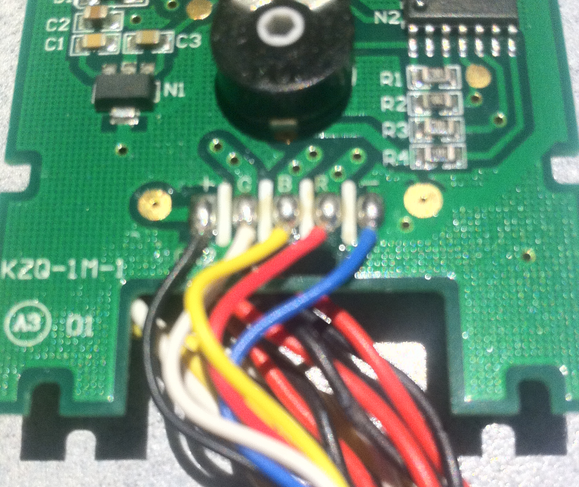
(plus) (G) (B) ® (minus)
Yeah i think two cables have been swapped (board is not the same, wires are linked to the back now, tell me if you need pictures).
I’ll try to get this right
Everything you have to do is connect G to G, B to B, R to R minus to GND and plus to VCC regardless of the colors
Ok seems to be Working with green and blue swapped (colors are wrong though). I tried to swap them back but it’s not working