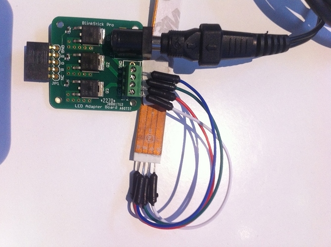
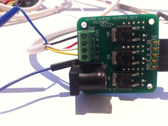
The BlinkStick Pro Led Adapter is supposed to be easier to install on a Dioder, but i can’t see any tutorial on how to install it on Ikea’s product on your website. Did i missed something ?
Hey,
seems there is no tut for this at the moment.
Here is how the connection to the Dioder LED Strip worked for me:
Strip / LED-Adapter
R / R
G / G
B / B
W / VCC
Power Supply: (-) -(o- (+)
Set the mode of the BlinkStick Pro to Mode 1 (Inverse).
For me it does not work with the new BlinkStick Client 2.0 but with BlinkStick Status it does.
I hope it helps.
So to do this i have to unplug totally the remote right ? And solder the cable to the adapter right ?
Adapter does not require any soldering. It has terminal and you can use a fine screw driver to screw the stripped connector wires directly to the LED adapter. DIODER uses very specific connectors to connect the LED strips. I’ll make a tutorial soon.
Oh yeah right i didn’t saw that. So i unplug the remote and plugit in the adapter and boom ?
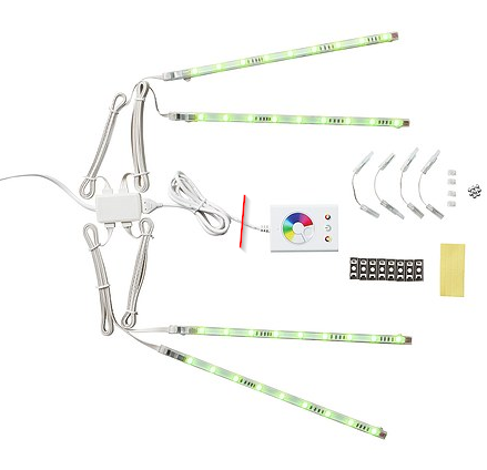
You won’t be able to plug it in directly. You will need to cut the wires. If you want to use the 4 way splitter of the DIODER, then you need to cut here anywhere on the wire:
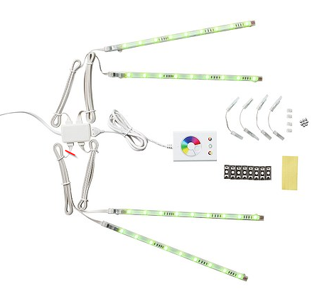
If you want to have all LEDs connected in series, then you need to cut here and link the LED strips together witch links provided by the DIODER:
You can reuse the power supply of the DIODER.
DIODER is quite expensive, but you can use any other RGB LED strip that looks like this and costs three times less:
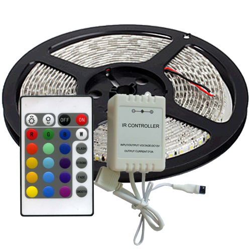
They also have connectors that can easily attach to the LED adapter board without the need to solder anything.
I´m using a Dioder with one flexible LED strip and a universal power supply.
Maybe it is not the recommended way but it works fine :). Any objections @arvydas?
Can i have a picture of the dioder too ? i don’t understand everything here 
I already have dioder so i’m gonna use it. Ok, cut the cable, screw cable in, done. Need for power supply for the adapter ?
OK, here is the wiring regarding Arvys first solution with the 4 way splitter:
Cut the cable as shown. Normally you will find 5 wires, blue, black, white, yellow and red.
Connect the wires to the LED adapter as follows:
Black: VCC
Red: R
White: G
Yellow: B
Blue: GND
Mode of the BlinkStick Pro again must be 1 (Inverse).
I hope this will help.
Yes. Thank you for this explanation. I think you talked about a power supply ? If i plug this into my computer via Blinkstick pro I don’t need one right ?
@gryfenflash you can reuse the DIODER power supply as it should plug in directly into the adapter board.
@p0ke I don’t think you need to connect the blue ground cable as it should work without it.
I’m gonna use this to get Ambilight on my pc. SO let’s recap to see if i have everything right:
-Cut the wire and plug them in Adapter
-PLug adapter into blinkstick pro
-blinkstick goes in computer
-Power supply goes in adapter ???
Does not work without blue for me.
Correct order should be like this:
- Everything DISCONNECTED
- Cut wire and connect to LED adapter as described by @p0ke
- LED Adapter must be connected to the BlinkStick Pro
- Connect Blinkstick Pro with LED adapter to the computer
- Connect power supply to the LED adapter
Need to check but can’t find a DIODER set in the office now. Very strange as it shouldn’t require the ground to be connected, because LEDs have only VCC and R, G and B pins.
Ok so no more power supply into Dioder, got it.
Well thank you, i managed to understand everything.
I’ll try without ground and see how it works.
Thanks again for your help everyone
Only as a very simple help:
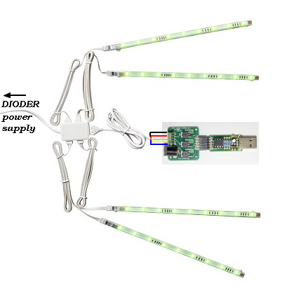
So there is no need for a additional power supply.
No problem for me 

