Dioder power supply doesn’t fit in Adaptater 
DIODER POWER SUPPLY fit in DIODER ADAPTER. If not, then you need to call IKEA!
I think you still want to put the DIODER Power Supply direktly in the BlinkStick adapter what of course does not work!
Please take a look at my schematic, there is no Power Supply at the LED Adapter!
Edit: Updated my schematic above with an additional hint.
Well it looks like i have everything right here, and nothing lights up (i’m in inverse mode)
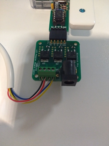
Hmmm… Wired like I have shown in the photo above?
Black: VCC
Red: R
White: G
Yellow: B
Blue: GND
Even if Arvy says there is no need for the blue one 
Yes, everything seems right
After you opend this thread I´ve tried it with a new Dioder and I know have a nice Ambylight for my Monitor. Maybe IKEA changed something regarding the colors of the wires or so…For me it works perfect like shown in the posts…
You have the Dioder with 4 strips, right? Not with the 4 buttons?!?
Yes of course.
Which wires could’ve been swapped ?
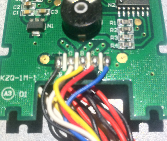
Open the controller of the Dioder and take a look at the wires.
Yup. Alright i see:
-Black linked to B
-Yellow linked to Y
-White linked to W
-Red linked to R
-Blue linked to B
Does this helps you ?
The controller must be different… this is how it looks to me:

(plus) (G) (B) ® (minus)
Yeah i think two cables have been swapped (board is not the same, wires are linked to the back now, tell me if you need pictures).
I’ll try to get this right
Everything you have to do is connect G to G, B to B, R to R minus to GND and plus to VCC regardless of the colors
Ok seems to be Working with green and blue swapped (colors are wrong though). I tried to swap them back but it’s not working
The colors of the wires doesnt matter. IKEA does not make it that easy. You have to look at the labels.
I just did, you have
B-W-Y-R-B and i have
B-Y-W-R-B
So i plugged them like this but it seems like green and blue are inverted
Ok i re-re-re-reinverted the cable so i have everything like it should be AND IT WORKS (seems like ground cable was not touching the plate on top of everything)
Thank you kindly for you really fast answers,
Do you have a tutorial for setting up ambilight now ? (i promise i’ll stop annoying you after that)
No problem, I like to help, sorry for the inconvenience. So write your wiring down for the next time 
Ambilight for me is just a backlight, so I did nothing more than starting the BlinkStick Client and chose the color I want. For me the real Ambilight function in BlinkStick Client does not work at the moment.
But you could try it yourself. Add a new notification “Ambilight” in the BlinkStick Client software and see if it works for you.
No it does not. I’ll see what the internet has to offer me for that
For future reference, this is my wiring setup for a 2015 Ikea dioder with the LED adapter, the blue is connected to GND from underneath although I haven’t tried without it.
VCC - Black
R - Red
G - White
B - Yellow
GND - Blue
My dioder controller only has the colours of the wires labelled inside so the colours do seem to matter now.
Hey guys,
Sorry for reviving this topic, but I used it to connect the Blinkstick pro with my Dioder through the adapter.
You say that if I cut the ‘data’ cable, which comes from the dioder controller I can use the Dioder’s own power supply. Right now it works magnificently with an external 12V power supply connected to the LED adapter, but not with the original power supply connected to the splitter.
Am I doing something wrong? Right now the ground is not connected to the LED adapter (just +, R, G, B). Can this be a problem? If I need to connect the ground as well, what would be the best place for it?
cheers

