Blinkstick on breadboard

I try to control it remotely but there is a problem.
I registered a new device and when I run the python script I can see that my device is online.
I select a color and receive on Terminal something like that: “Received color: #5e4431” but nothing happens on my led.
I replaced the r,g,b with random values in this line:

bstick.set_color(r, g, b)

having something like that

bstick.set_color(50, 50, 200)

but nothing happened. Then replaced the above line with this:

bstick.set_random_color()

and each time I select a new color my led turns on with a new random color.


edit:
fixed this by changing the above line to:

bstick.set_color(red=r, green=g, blue=b)

Oh, thanks for this! I’ve updated the example script with the fix you suggested.

i’ve just been dealing with the same issue. really enjoying working with blinkstick. i’m using it with neopixels strip.

if you run blickstick --info

it returns:
Traceback (most recent call last):
File “/usr/local/bin/blinkstick”, line 308, in
sys.exit(main())
File “/usr/local/bin/blinkstick”, line 254, in main
print_info(stick)
File “/usr/local/bin/blinkstick”, line 78, in print_info
print(" Manufacturer: {0}".format(stick.get_manufacturer()))
UnicodeEncodeError: ‘ascii’ codec can’t encode character u’\u0409’ in position 0: ordinal not in range(128)

Could you make the blinkstick python ‘first timer’ for Mac docs clearer, its missing the USB lib downgrade.

Did the downgrade sort the issue? I’ll probably release a new version of BlinkStick Python module in order to link it directly to b1 release of PyUSB.

yes. downgrade solved it. i’d recommend the PyUSB downgrade by default as it just breaks too many things.

@marks thanks for your help! I released a new version of BlinkStick Python module to address this issue. Installation should be a lot more smooth now :smile:

Hello folks,
I’ve build the Blinkstick Pro using a ATtiny45-20 on a breadboard. Got the firmware downloaded and compiled using the cli tools from Atmel Studio 6 version 6.0.1996 SP 2 with ARM Toolchain 4.7.0.59 - GCC 4.7.0 successfully for target attiny45. Also generated the eeprom.hex, flashed this and main.hex via AVR.Dragon. Set the fuses to LowFuse = 0xE1 and HighFuse = 0xDD. All looks fine until I give it a try … All I get in Windows 7 is “Unknown Device” if I plug it into a USB Port. If I try it on my Raspberry Pi I find usb read error like this

Feb 18 17:55:17 raspberrypi kernel: [ 4190.628944] usb 1-1.3: new full-speed USB device number 4 using dwc_otg
Feb 18 17:55:17 raspberrypi kernel: [ 4190.708988] usb 1-1.3: device descriptor read/64, error -32
Feb 18 17:55:17 raspberrypi kernel: [ 4190.898958] usb 1-1.3: device descriptor read/64, error -32
Feb 18 17:55:17 raspberrypi kernel: [ 4191.088958] usb 1-1.3: new full-speed USB device number 5 using dwc_otg
Feb 18 17:55:17 raspberrypi kernel: [ 4191.168977] usb 1-1.3: device descriptor read/64, error -32
Feb 18 17:55:17 raspberrypi kernel: [ 4191.359496] usb 1-1.3: device descriptor read/64, error -32
Feb 18 17:55:18 raspberrypi kernel: [ 4191.548992] usb 1-1.3: new full-speed USB device number 6 using dwc_otg
Feb 18 17:55:18 raspberrypi kernel: [ 4191.968882] usb 1-1.3: device not accepting address 6, error -32
Feb 18 17:55:18 raspberrypi kernel: [ 4192.049010] usb 1-1.3: new full-speed USB device number 7 using dwc_otg
Feb 18 17:55:18 raspberrypi kernel: [ 4192.468886] usb 1-1.3: device not accepting address 7, error -32
Feb 18 17:55:18 raspberrypi kernel: [ 4192.469106] hub 1-1:1.0: unable to enumerate USB device on port 3

in the syslog.

Do you have any hints for me? What am I doing wrong?

BTW: On the RPi I install the python-pip package and than via “pip install blinkstick” the python-blinkstick stuff. Also executed “blinkstick --add-udev-rule” and rebooted. The command “blinkstick --info” show nothing … my blinkstick is not recognised by the OS.

Kind regards,
birko

If you are making a Pro based BlinkStick on a breadboard, you need to use the pro branch on Github. Did you use this one?

Thanks! You are right. I’ve grabed the wrong firmware. Also the pro firmware will not fitt on a ATtiny45.

Yes, but I think you can minimize the API to support ATTiny45. First thing to do is to drop LED count to 32, this might be sufficient to fit into 45.

Today I got the ATTiny85 so nothing to change in the code. Will get a IKEA Dioder and play with it at the weekend. With a single NeoPixel it is currently working very well. ;-D

Thanks for your support!

Thanks for letting me know it works for you. Have fun! :smiley:

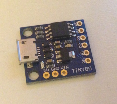
I got one of these tiny85 dev boards and I thought it would be nice to use it as a blinkstick.

I In the Makefile the first line says:
SHELL=C:/Windows/System32/cmd.exe
I removed it since I’m working on a Mac and it was giving me an error.
I tried to upload the firmware with
```make deploy``
and there wasn’t any error.
When I connect this board with a microusb cable it cannot be recognized.
I think it’s the same circuit with blinkstick except the resistor values.
What could be the problem? Is it possible to use it as blinkstick? Has anyone tried a board like this with blinkstick firmware?

Do you have the schematics for the board? The firmware will probably have to be adjusted and I need to know how the USB signals are connected to ATTIny85.

I don’t have the schematic but I checked it with my multimeter and it has the same connections with blinkstick.
The only differences are the values of the resistors. The resistor between ATTiny pin2 and D- is 220 Ohms. The same for the resistor between pin 3 and D+. The resistor between 5V and D- is 1K.
There are also 2 leds with resistors and a 78l05 voltage regulator but I don’t think they are relevant.

I think this board is a Digispark clone. As I have read, depending on the fuses settings, the reset pin might or might not be disabled. If it was disabled would I be able to upload the blinkstick firmware?

How did you try to upload the BlinkStick firmware to the device? Did you use the provided USB connection and uploaded it that way or did you use “crocodile” clip on the ATTiny85 chip and external ISP programmer like USBTinyISP?

I upload it using an Arduino Uno as ISP programmer by connecting MOSI,MISO,SCK,RESET, VCC and GND.
This is what I got:

avrdude -c arduino -P /dev/tty.usbmodemfd141 -b 19200 -p attiny85  -U flash:w:main.hex:i

avrdude: AVR device initialized and ready to accept instructions

Reading | ################################################## | 100% 0.01s

avrdude: Device signature = 0x1e930b
avrdude: NOTE: "flash" memory has been specified, an erase cycle will be performed
         To disable this feature, specify the -D option.
avrdude: erasing chip
avrdude: reading input file "main.hex"
avrdude: writing flash (4210 bytes):

Writing | ################################################## | 100% 7.03s

avrdude: 4210 bytes of flash written
avrdude: verifying flash memory against main.hex:
avrdude: load data flash data from input file main.hex:
avrdude: input file main.hex contains 4210 bytes
avrdude: reading on-chip flash data:

Reading | ################################################## | 100% 4.35s

avrdude: verifying ...
avrdude: 4210 bytes of flash verified

avrdude: safemode: Fuses OK (H:FE, E:DD, L:E1)

avrdude done.  Thank you.

avrdude -c arduino -P /dev/tty.usbmodemfd141 -b 19200 -p attiny85  -U hfuse:w:0xdd:m -U lfuse:w:0xe1:m

avrdude: AVR device initialized and ready to accept instructions

Reading | ################################################## | 100% 0.01s

avrdude: Device signature = 0x1e930b
avrdude: reading input file "0xdd"
avrdude: writing hfuse (1 bytes):

Writing | ################################################## | 100% 0.02s

avrdude: 1 bytes of hfuse written
avrdude: verifying hfuse memory against 0xdd:
avrdude: load data hfuse data from input file 0xdd:
avrdude: input file 0xdd contains 1 bytes
avrdude: reading on-chip hfuse data:

Reading | ################################################## | 100% 0.02s

avrdude: verifying ...
avrdude: 1 bytes of hfuse verified
avrdude: reading input file "0xe1"
avrdude: writing lfuse (1 bytes):

Writing | ################################################## | 100% 0.02s

avrdude: 1 bytes of lfuse written
avrdude: verifying lfuse memory against 0xe1:
avrdude: load data lfuse data from input file 0xe1:
avrdude: input file 0xe1 contains 1 bytes
avrdude: reading on-chip lfuse data:

Reading | ################################################## | 100% 0.02s

avrdude: verifying ...
avrdude: 1 bytes of lfuse verified

avrdude: safemode: Fuses OK (H:FE, E:DD, L:E1)

avrdude done.  Thank you.

ruby increment.rb
/Library/Ruby/Gems/2.0.0/gems/hex-0.2.0/lib/wo_oo/electronics/intel_hex_grammar.rb:101: warning: assigned but unused variable - line_data
BS000002-2.2
avrdude -c arduino -P /dev/tty.usbmodemfd141 -b 19200 -p attiny85  -B 3 -U eeprom:w:eeprom.hex:i

avrdude: AVR device initialized and ready to accept instructions

Reading | ################################################## | 100% 0.01s

avrdude: Device signature = 0x1e930b
avrdude: reading input file "eeprom.hex"
avrdude: writing eeprom (512 bytes):

Writing | ################################################## | 100% 28.35s

avrdude: 512 bytes of eeprom written
avrdude: verifying eeprom memory against eeprom.hex:
avrdude: load data eeprom data from input file eeprom.hex:
avrdude: input file eeprom.hex contains 512 bytes
avrdude: reading on-chip eeprom data:

Reading | ################################################## | 100% 5.29s

avrdude: verifying ...
avrdude: 512 bytes of eeprom verified

avrdude: safemode: Fuses OK (H:FE, E:DD, L:E1)

avrdude done.  Thank you.

The programming section looks good, but I’m afraid there is not much I can help you with in regards to why it’s not working for you. My only suggestion is to double check that the D+ and D- lines are identically connected as in BlinkStick, but other than that without the schematics it’s difficult to give any suggestions :confused:

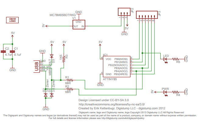
The schematic is the same with this

With R1=R2=220 and R3=1K.
Could different R values require modification on firmware?

The D+ connection to ATTiny85 is different. You need to update this lines with correct value:

It should be 4 according to the schematic.